It’s a 3D World
By Stephen Cherlet and Manoj Kumar
Innovation & Technology 3d technology 3d world cad tool design teams design tools emerging technology hard copy legacy data paper drawings spare partsA fun part of being a consultant is visiting different companies, which allows for comparison between organizations, and the ability to find organizations with innovative ideas. However, you also get to where their is still opportunities for improvement or progress.
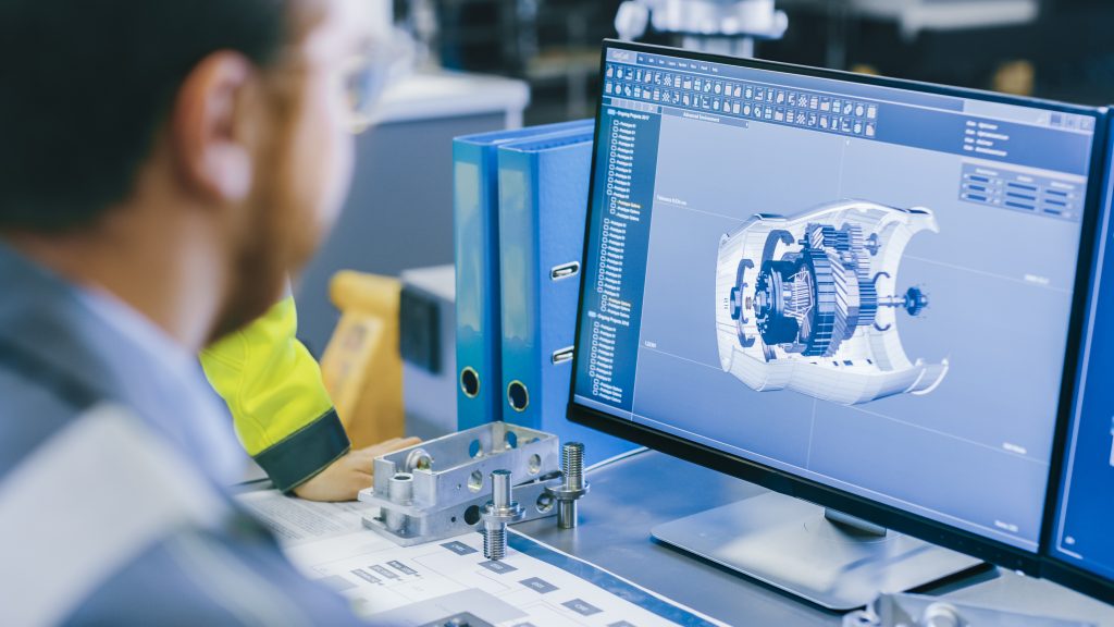
Photo: ©Gorodenkoff/Adobe Stock
Back when studying engineering, everything was pencils, t-squares, set squares, ovals and perhaps a flex-curve. My first job at the aircraft factory, the design team had massive tables and full-sized drawings of the “master lines” of the aircraft. The print room worked with aperture cards and printed massive amounts of paper. Working as a support engineer, we had to ask for a fresh print (hard copy) to check even a few dimensions. Back then, there was no such thing as looking at information on a screen except for standard items like for fasteners, washers, and rivets, all of which could only be viewed on microfiche, microfilm, or in a parts catalogue.
Back in those days, 2D was expensive and 3D design tools cost fortunes. I remember at various subsequent employers we had two designs teams – one with drafting tables and one with a 3D CAD (Computer Aided Design/Drafting) tools. As 3D was emerging technology at the time, the hardware and software was so expensive firms could not afford to convert all at once.
Surprisingly, a lot of paper drawings are still in use today. Though I seldom encounter companies generating new paper-based drawings, the legacy data still remains intact as hard copy. Typically the vellum and old prints have been scanned making the drawing available in an electronics format, usually through PDF, these are typically old items that are not in production but needed for spare parts. They can be part of really old designs. When the need for change arises, these companies may take the opportunity to re-draw the part using a CAD tool. This slowly brings everything into a digital world. Depending on the item, firms may only re-create the part in 2D. This is especially true if the part is not used in a higher assembly, eliminating the value of creating the item in 3D to check for fit.
2D was the rage
Eventually, the cost of both hardware and software came out of the stratosphere. Instead of paper and electronic design/drafting teams, we had a combination of 2D and 3D teams. Paper was slowly being phased out. With 2D, there was some improvement in overall drafting time. Derivative parts were easier to create. Electronic information sharing got simpler both internally and externally. Then, and still today, companies print a hard copy for signature. This prolongs the concept of paper as the master data source.
Moving to 3D
Although 3D design does seem to be expensive still, hardware costs have come down. For the same cost as a 1980s word processor, you can get a good workstation today. Gone are the days of high-end reduced instruction set computer (RISC) workstations from various companies. Now regular PC hardware, properly specified, can get the job done. Cost is not a real obstacle from a hardware perspective. Software, and its accompanying maintenance, or annual licences fees, can still be a concern for small to medium sized enterprises, although there are lower cost products available that are affordable.
But what about the benefits?
Beyond the original benefit of being able to model full assemblies to check for interference and fit, there is a cornucopia of tools able to import a 3D model for a variety of analyses.
Also, we cannot forget about industrial engineering. Computer aided manufacturing (CAM) software facilitates the creation of numerical control programs for the production of machined parts, laser and water jet cutting, electrical discharge machining (EDM) and robotic welding. In addition to generating tool paths, the software can often check for interference between part and machine.
If the fixtures have been designed in 3D, then the process team can often also check for machine, or tool, interference with the fixture. Not only is there a decrease in the cycle time to prepare for production, there is a decrease in tool-part-fixture collisions potentially causing serious damage, injury or delay.
From the design side, having a 3D model lends itself to design validation through finite element analysis (FEA). FEA can be used to predict how a product will reacts to real-world forces, vibration, heat, and fluid flow. FEA guides designers as to whether a product will break, and at what point, or work the way it was designed.
For parts involving castings, the ability to simulate metal flow and cooling for the parts after pouring is a great feature. High end software tools can all contribute to improving the designs of castings, improving product quality and yield. Such analysis could detect part shrinkage, and directional solidification, resulting in the potential to add a riser(s) at critical locations in the mold. It is better to find problems, and resolve them in advance, instead of on the foundry floor.
The availability of the digital object is a key to supporting supplier collaboration for any process. Some foundries will offer to run the casting simulation for you if the 3D model is provided. Machine shops, and many suppliers with robotic processes (like welding or painting), will also appreciate being supplied with a model.
With the advent of 3D printing or additive manufacturing, companies can send the digital model to a supplier and receive a physical part back. Also, the option to invest in the printing equipment and bring the process in-house, is available. New printing process are permitting the use of advanced materials. Direct metal laser sintering (DMLS) is an industrial metal 3D printing process that “prints” fully functional metal parts in days from start to finish. A range of metals produce final parts that can be used for end-use applications. Those materials now include cobalt chrome, titanium, Inconel, tantalum, tungsten, stainless steels, and custom alloys.
Where to next?
Simulations can be produced as instructional videos. They can guide machine operators with respect to fixture installation on a machine, part placement in the fixture, and provide a preview for the tool path. In the assembly department, videos can be used as general training aids or for specific tasks. Still images from any of the simulation can also be used. If you have customer serviceable products, the in-house assembly videos can be turned into instruction aids for customers or authorized repair centres. Ultimately, all of this can be done in a completely immersive virtual reality environment.
How do I get there from here?
For those who still have hard copy documents, there are a variety of services to digitize your information. Scanning services to produce 2D vector drawings have been around for a long time, and the quality of the output has improved. Some services will offer human expertise to review and clean up the newly vectorized results.
The real issue is getting from paper, or 2D CAD, to 3D. This still takes a human being, so, if you are not doing this in-house, you will need to contract a services company. Choosing a business partner with the correct experience is paramount to a successful conversion project. A critical success factor is to have an agreement on the key parameters of the model, dimensioning standards, defined use of layers, and tolerances on precision. This is needed to ensure the quality of the result and to avoid over specifying needs, which can result in massive file sizes.
Another option is to use 3D scanners and create the basic model from an actual part. Scanners have come down in price but are still expensive. Depending on the part, some holding fixtures could be needed, but it is still a faster way to get started on your digitization project. The downside is the model will reflect the as-is dimension of the actual part, not nominal dimensions with tolerances. That will have to be applied afterwards.
Some firms are scanning plants and piping to generate models of the “as-built” configuration. This provides the foundation for documenting the state of the building and can be integrated with EAM and CMMS.
The glue that binds all this digital information together is the product lifecycle management (PLM) system. PLM provides the relationship of all the data to each other, manages changes and allows you to execute at speed.
Therefore, it is becoming a fully digital world and the time has come to embrace it. From concept to production, all the processes in between are accomplished easier digitally. Digital supports both customer and supplier collaboration. Mock-ups and models can be produced for visualization to aid in the design process. At the other end of the supply chain, suppliers can get ready for production, and produce faster, with a full 3D model.
Take full advantage.
_______________
Stephen Cherlet is a senior management professional with 35+ years of experience. Stephen is the owner/founder of FarStar S.A.C. Consulting. He is also the Chair of the National Board of Directors at Supply Chain Canada. He can be contacted at stephen@farstarconsulting.com.
Manoj Kumar is a senior management professional with 22+ years of experience. He is working as a Business Head at Inde Dutch Engineering & Aerospace Services Limited (IDEAS). Manoj can be contacted at manoj.k@ideasengg.com.