Maintaining motor drives: Five essential tests to gauge performance
By Fluke Corp.
Innovation & Technology Manufacturing Fluke manufacturing TroubleshootingMake maintenance a priority to ensure system uptime.
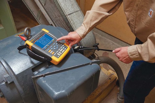
Fluke’s MDA 510 and 550 (pictured) combine the functions of a meter, handheld oscilloscope and recorder guided by instructions from motor drive experts. On-screen prompts, clear setup diagrams, and step-by-step instructions guide users through the essential tests.
PHOTO: FLUKE
Motor drives transform constant voltage from the main AC power supply into a voltage that varies to control motor torque and speed. They’re higher efficiency than directly driven motors, providing energy cost savings, higher production performance and longer motor life.
Troubleshooting and testing motor drives, also known as variable frequency drives (VFD), variable speed drives (VSD) or adjustable speed drives (ASD), can be challenging because work history for the equipment is often incomplete or missing.
Advances in testing technology have eliminated some of the challenges. Newer instruments provide documentation capabilities of the process at each step, storing reports for comparison against subsequent tests to get a bigger picture of motor drive maintenance history.
Getting to the root cause of a failure or performing a routine preventive maintenance check is best done with a set of standard tests and measurements at key points within the system.
Here are five essential troubleshooting tests:
1. Drive input. Analyzing the power going into the motor drive determines if a feeder circuit to the drive has distortion, disturbance or noise that may be affecting power ground.
If nominal rated voltage and the actual supplied is more than 10% out of range, there could be a supply problem.
Determine if the input current is within the maximum rating and the conductors are suitably sized.
More than a 0.5 Hz difference between measured and specified could cause problems.
Is harmonic distortion within an acceptable level? Flat-top waveforms, for example, suggest a nonlinear load is connected to the same feeder circuit. Over 6% indicates a potential problem.
Check the voltage unbalance at the input terminals to ensure the phase unbalance is less than 6% to 8%, and the phase rotation is correct. A reading over 2% can lead to voltage notching, tripping the overload fault protection or disturbing other equipment.
A current unbalance reading of over 6% could point to a problem within the inverter of the motor drive.
2. DC bus. High ripple voltage may be an indicator of failed capacitors or incorrect sizing of the connected motor.
Determine if the DC bus voltage is proportional to the peak of the input line voltage. Except for controlled rectifiers, it should be about 1.31 to 1.41 times the RMS line voltage. A low reading caused by low input mains voltage or input voltage distortion such as flat topping trips the drive.
Distortion or error in peak amplitude of the line voltage can cause an over- or under-voltage error. A DC voltage reading +/- 10% from the nominal voltage indicates a problem.
Determine if the peaks of the AC ripple have a different repetition level. Ripple voltages above 40 volts can be caused by malfunctioning capacitors or a drive rating too small for the connected motor or load.
3. Drive output. Testing the drive output offers clues to problems within the drive circuits.
Determine if the voltage and current are within limits. High output current may make the current run hot, decreasing stator insulation life.
Check the voltage/frequency ratio (V/Hz) to ensure it’s within the motor’s specified limits. A high ratio causes overheating; a low ratio makes the motor lose torque. Stable frequency and unstable voltage points to DC bus problems; unstable frequency and stable voltage suggests switching (IGBT) problems. Unstable frequency and voltage indicate potential issues with the speed control circuits.
Check voltage to frequency ratio (V/F), and voltage modulation. High ratio measurements can lead to overheating. At low V/F ratios, the motor may not provide the required torque at the load to sufficiently run the intended process.
Check for voltage modulation using phase-to-phase measurements. Peaks higher than 50% nominal voltage can damage motor winding insulation and cause the drive to trip.
Check the steepness of the switching impulses. The rise time is indicated by the rate of voltage changeover time and should be compared to the motor’s specified insulation.
Test the switching frequency with phase to DC. The signal floating up and down may indicate an issue with electronic switching or grounding.
Voltage unbalance should not be more than 2% (preferably measured at full load). It causes current unbalance, resulting in excessive heat in the motor winding. Single phasing causes a motor to run hot, not start after stopping, lose significant efficiency and potentially results in damage to the motor and its connected load.
Current unbalance in three-phase motors should not exceed 10%. Large unbalance while voltage is low points to shorted windings or phases shorted to ground. It also causes drive tripping, high motor temperatures and burnt windings.
4. Motor input. Incorrect cabling selection can result in both drive and motor damage due to excessive reflected voltage peaks. These tests are mostly identical to those for drive output.
5. Motor shaft voltage. Voltage pulses coupling from a stator to the rotor causes a voltage to appear on the rotor shaft. When the insulating capacity of the bearing grease is exceeded, flashover currents occur causing pitting and fluting of the bearing race, damage that can cause a motor to fail prematurely.
Measure the voltage between the motor chassis and the drive shaft to detect the presence of destructive flashover currents. Impulse amplitude and count of events will enable you to take action before failure occurs.
Motor systems drives deliver significant cost savings related to electricity use. Applying these tests to motors driving mechanical loads will help to ensure efficiency and performance are at peak levels while uptime is maximized.
This is an edited version of a longer article contributed by Fluke Corp., a manufacturer of test, measurement and diagnostic equipment based in Everett, Wash. Fluke Electronics Canada LP is based in Mississauga, Ont. Visit www.fluke.com/en-ca.
This article appeared in the November-December 2020 print edition of PLANT Magazine.