The 101 on steam turbines: What you need to know about lube systems
By Dresser-Rand
Industry MRO Manufacturing lubrication maintenance manufaturing Siemens STLEDresser-Rand Canada explains how the lubrication systems work and highlights problems that would require troubleshooting.
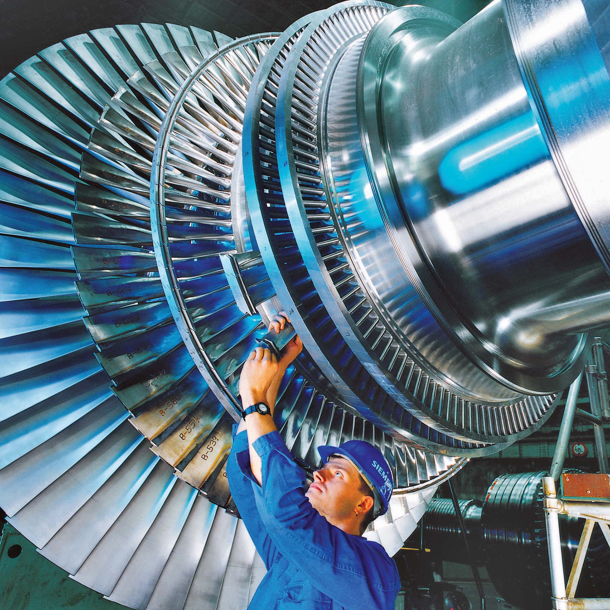
A modern Siemens steam turbine.
PHOTO: SIEMENS/CHRISTIAN KUHNA
Steam turbines extract thermal energy from pressurized steam to do mechanical work on a rotating output shaft. These complex machines – found in a range of industrial markets including oil and gas, paper, steel and energy – have many parts. Correct lubrication ensures they operate efficiently and minimize friction while carrying heat away from thrust and journal bearings, and from gear meshes.
There are three types – ring oil lubrication, saddle pump and force-feed pressurized systems.
Ring oil lubrication carries oil from the sump to the turbine bearings. Typically one oil ring is used per journal bearing, providing lubrication during start-up, normal operation and coasting down. The oil level in the sump is critical to proper operation. Ring oil lube systems may use fin type coolers submerged in the oil sump or a water jacket around the sump. Sump temperature must not exceed 82 degrees C. The use of ring oil lubrication is limited by speed (maximum 5,000 rpm) and temperature.
A saddle pump lube type is a supplementary system in which an oil pump is used to circulate oil through the bearing housings. This type is typically used on small, single-stage turbines where oil temperatures exceed 82 degrees C. The saddle pump is usually mounted on the coupling end bearing cap and is shaft-driven through spur gears. Standpipes or equalizer pipes are used to maintain proper oil levels in bearing housings. When sump cooling is not adequate, an external oil cooler may be installed. The system pressure is typically 3 to 5 psig.
In force-feed pressurized systems, an oil pump sends pressurized oil directly to the turbine bearings. This type is used when operating speed, horsepower or temperature exceed the practical limits of ring oil or saddle pump systems.
System components
Lube oil system components include a pump, tank, cooler, filter and control valves.
Pressurized oil is circulated throughout the lube oil systems that may contain main, auxiliary and emergency oil pumps. The most common types are positive displacement gear and centrifugal oil pumps, driven by the steam turbine, AC or DC electric motors, or shaft-driven. Shaft-driven oil pumps are direct-drive or driven through a gear reducer or increaser. If the main oil pump is shaft-driven, oil rings or an auxiliary oil pump are used during start-up and run-down. Main and auxiliary oil pumps have identical output ratings. Emergency oil pumps are typically driven by DC motors and are used only for lubrication during run-down operation.
A positive displacement gear type oil pump causes lubrication fluid to move by trapping a fixed amount of it and then forcing that trapped volume into the discharge pipe. Gear pumps use two meshed gears rotating in a closely fitted casing. The fluid is pumped around the outer periphery and trapped in the tooth spaces. The pump output is given as flow rate in gallons, or litres, per minute at a given pressure.
In centrifugal oil pumps the rotation of the pump impeller delivers kinetic energy to the lubrication fluid through centrifugal force. The impeller slings the liquid out of the volute, forcing it to discharge from the pump by converting velocity to pressure.
Lube oil tanks can be located in the equipment base plate, the machine casing or at a separate place. Capacity is based on return time. A vent or vapour extractor eliminates air in the system. Tanks must also have a level indicator, drains, cleanout access, a fill opening, baffles and a degassing tray.
Shell-and-tube oil coolers will remove heat from the lubrication oil. Two fluids of different starting temperatures flow through a heat exchanger. One flows through the tubes and the other flows outside the tubes but inside the shell. Heat is transferred from one fluid to the other through the tube walls.
Oil coolers are designed to maintain lube oils at approximately 48 degrees C. Water is on the tube side and oil is on the shell side. To prevent contamination, the operating pressure on the oil side is higher than the water pressure.
Fouling must be avoided or kept in check. It occurs when a fluid goes through the heat exchanger and impurities precipitate onto the surface of the tubes. This reduces the cross-sectional area and interferes with the heat transfer across the exchanger. Applying an anticipated fouling factor ensures the cooler operates as designed.
Some designs allow removal of tube sheets for cleaning. An oil bypass line around the cooler with a temperature control valve regulates oil supply temperature.
Filters typically use replaceable paper elements to remove fine contamination from lube oil. Strainers use a reusable stainless steel mesh screen to remove coarse contamination. Most steam turbine lube oil systems use either a single filter system with an unfiltered bypass or a duplex system with a transfer valve and two oil filters in parallel.
The pressure differential between the filter’s inlet and outlet is monitored and may have an alarm point to indicate the need for a filter element change. In some cases additional filters with low micron elements are used to protect sensitive control system components.
Control valves regulate fluid pressure and temperature during operation. An oil pressure regulating valve is normally open. A downstream sensing line pipes the oil to the spring-loaded (open position) regulator diaphragm. When the oil pressure from the sensing line overcomes the spring setting the valve begins to close, reducing the oil pressure downstream of the regulator.
A normally closed backpressure regulating valve has an upstream sensing line. The outlet is piped to the oil tank.
Three-way thermostatic valves maintain a constant oil supply temperature after the oil cooler. They send the oil through the cooler, bypass the cooler, or do both. A temperature element and a spring open and close the valve.
Properly refined and highly filtered mineral oils must have high oxidation stability to prevent the formation of rust on metal parts. They must also be free of acid and alkali, and capable of separating rapidly from water; have a high viscosity index and minimum tendencies to oxidize or form a sludge when agitated at operating temperatures; or to emulsify or foam when agitated with water and/or air.
These include thicker horizontal flanges and improved bolting for better sealing, elimination of vertical flanges and improved materials better suited for repair, such as stainless steel. The benefits of case upgrades are the ability to properly maintain existing equipment, footprint, piping connections and spare parts.
Control upgrades (programmable logic controllers), instrumentation upgrades (probes, accelerometers, monitors) and seal upgrades also improve steam turbine operation. For instance, brush seals reduce leakage from stage to stage and enhance the function of conventional labyrinth seals. Reducing leakage results in more power from the available steam. It’s not uncommon to see a 0.2% to 0.5% improvement in efficiency.
Upgrading sleeve journal bearings to tilt pad reduces instability caused by oil whirl, allows uniform distribution of oil flow and provides adaptability to shaft movements. In many cases re-machining is not required.
Watch for these symptoms of trouble
Abnormal noise, or knocking. Caused by cavitation, inlet restrictions, such as clogged strainers or too small pipe diameters, and aeration (pump inlet air leaks or improperly sized reservoirs).
High fluid temperature. Caused by improper flow (restrictions to bearings, low system pressure) or improper cooling (oil cooler fouling, inadequate tank size). Temperature exceeding 82 degrees C damages seals, reduces fluid life through oxidation, and increases wear on bearings and other system components.
Low pressure. Caused by flow restriction, incorrect regulator or control valve set point, or incorrect pump sizing.
High pressure. Attributed to incorrect set points of regulator/control valve, and stuck valves. Other culprits are incorrect pump and piping sizes.
Water contamination. Identified by brown or milky appearance of the lubricating oil. Water increases the oil level. The formation of emulsion clogs filters and strainers, causes deposits on bearings and accelerates valve failure. Remedial measures include improving mechanical or brush seals, diligent regular steam seal maintenance, and improved air purge baffles in tanks.
Debris contamination. Results from rust, slag, dirt and leaves clogging filters and strainers, lines and passages, , and it accelerates valve failure.
The information featured in this condensed version of a technical paper is the property of Dresser-Rand Co., published here with permission from the presenters at a lubrication education day seminar hosted by the Society of Tribologists and Lubrication Engineers (STLE) in Hamilton. Dresser-Rand, a Siemens company, makes steam turbines for the oil and gas, paper mills, steel, energy and other industrial markets.
This article appeared in the January-February 2018 print issue of PLANT Magazine.